

There are three supported network connectivity methods:
Public internet is the default method for network connectivity.
VPN/IPSec tunnels and SBC configuration are required for this option.
For more information, see Real-Time Third Party Telephony Recording (Multi-ACD).
Overview
Cato SD-WAN is supported for secure, private connectivity between your data center and NiCE CXone Engagement Hub (Multi-ACD/Open).
SD-WAN (Software Defined Wide Area Network) uses centralized, policy-based routing to send traffic over the best available path in real time and prioritize important applications (such as voice and CTI).
Cato Networks provides SD-WAN edge appliances called Cato Sockets. You are responsible for choosing the sockets that match your performance and port needs.
Connectivity Models
There are two supported connectivity models available.
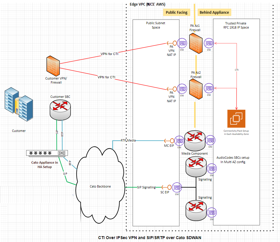
Model 1: CTI over IPSec VPN + SIP/SRTP over Cato SD-WAN
-
CTI traffic goes over IPSec VPN / Internet between your site and NiCE. You manage NAT and IPSec configuration for CTI.
-
SIP/SRTP traffic goes over Cato SD-WAN. Cato manages NAT and delivers SIP/RTP to NiCEin AWS.
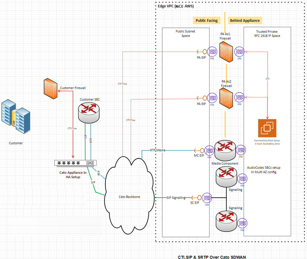
Model 2: CTI, SIP, SRTP all over Cato SD-WAN
-
All relevant traffic (CTI, SIP, RTP) passes through Cato Sockets.
-
Cato NAT and routing provide connectivity to NiCE in AWS for all flows.
-
This model simplifies your connectivity because all voice media and CTI use the same path.
Customer Requirements
To provide a stable and resilient connection, you are expected to meet the following requirements when deploying Cato Sockets.
High Availability and WAN
-
HA Sockets per Data Center
Deploy a pair of Cato Sockets in high availability (HA) at each data center.
Example: Two data centers require two HA pairs (one pair per site).
-
Redundant WAN / Internet Circuits
Provide at least two redundant Internet or WAN circuits at each site.
This supports path failover and keeps service available during outages.
-
Unique Public IPs for Tunnels
Assign each socket in an HA pair a unique public WAN IP.
These IPs are used to build secure DTLS tunnels to the nearest Cato PoP.
-
Symmetrical Cabling
Use mirrored LAN and WAN cabling on both sockets in each HA pair to ensure correct failover behavior and consistent performance.
Model-Specific Responsibilities
Model 1: You are responsible for configuring and maintaining NAT and IPSec for CTI.
Model 2: All traffic flows through Cato NAT.
Configuration
The NiCE Professional services team will work with you to complete these steps in the Cato portal.
For more information, see Cato Networks Knowledge Base.
Step 1: Deploy and Register Cato Sockets
-
Rack, power, and cable the sockets at each data center.
-
Add them to the Cato Cloud and assign each pair to the correct Site.
-
Make sure each site is configured as an HA deployment, and each socket uses a unique public IP.
Step 2: Configure LAN Networks
-
In the Cato Orchestration Portal add the LAN ranges that contain:
-
Your SBCs
-
Media servers
-
CTI servers (for Model 2, and for any flows that must cross Cato)
-
-
Each data center should have its own site and its own LAN network definitions.
Step 3: Allocate Public IPs for NAT
-
In the Cato Orchestration Portal, allocate two public IP addresses per site for NAT.
Base licenses typically allow up to 3 IPs per account; more addresses may add cost.
-
Choose the PoP location closest to each site for best performance.
Step 4: Configure Internet Network Rules (Outbound)
-
In the Cato Orchestration Portal, for each site:
-
Use the two NAT IPs you allocated to maintain PoP level HA.
-
Set Source to the SBC, media, and (where relevant) CTI LAN networks.
-
Create Custom Applications as needed for:
-
NiCE CXone Engagement Hub (Multi-ACD/Open) signaling IPs and ports
-
NiCE media IPs / RTP ranges
-
CTI firewall NAT IPs (Model 2 only)
-
-
Set Bandwidth priority high for SIP/RTP and CTI.
-
Select the NAT method and associate it with the two closest PoP allocated IPs.
-
Keep a default Internet rule for any other outbound traffic from your LAN.
-
Step 5: Configure Internet Firewall (SIP/RTP)
-
In the Cato Orchestration Portal, in the Security area, create allow rules:
-
Source: Your SBC IPs (and media IPs if required)
-
Destination: NiCE CXone Engagement Hub (Multi-ACD/Open) SBC IPs
-
Service/Ports: SIP and RTP as defined by NiCE
-
-
Make sure an implicit deny rule remains at the bottom to block any other traffic.
Step 6. Configure Remote Port Forwarding (Inbound)
For inbound traffic such as CTI from NiCE to your environment (especially in Model 2):
-
In the Cato Orchestration Portal, in the Security area, create rules that:
-
Use the Cato PoP IPs/ports exposed to NiCE.
-
Forward to your internal CTI servers or SBCs on the required ports.
This ensures that inbound CTI and SIP refreshes are routed correctly to your systems.
-
-
For Model 2, NiCE updates Engagement Hub (Multi-ACD/Open) VPN firewall rules to allow CTI traffic from NiCE CTI servers to your Cato PoP IPs defined in these rules.
Step 7: Validation and Testing with NiCE Professional Services
Once configuration is complete, schedule a joint test session with your team and NiCE Professional Services.
After validation, the Cato SD-WAN connectivity is considered ready for production use with NiCE Engagement Hub (Multi-ACD/Open).
Overview
AWS Public Direct Connect is a dedicated network service that creates a private connection between your data center and AWS. This connection does not use the public internet, so it provides more stable performance and lower delay.
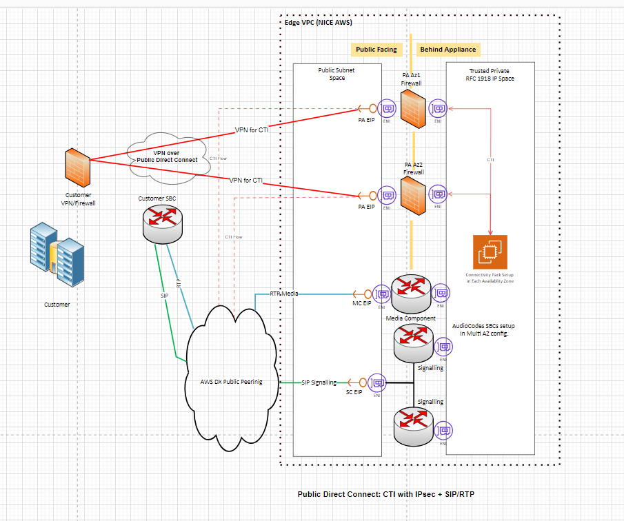
This procedure describes how to set up a Bring Your Own Connectivity (BYOC) model using AWS Public Direct Connect for Engagement Hub (Multi-ACD/Open). This allows your CTI (Computer Telephony Integration) signaling and SIP/RTP media traffic to travel over a private, dedicated path.
Connectivity Models
This is a Bring Your Own Connectivity (BYOC) model. You are responsible for setting up and managing the AWS Public Direct Connect connection, including routing and network design. NiCE does not create or manage Direct Connect for you.
There are three connectivity models available:
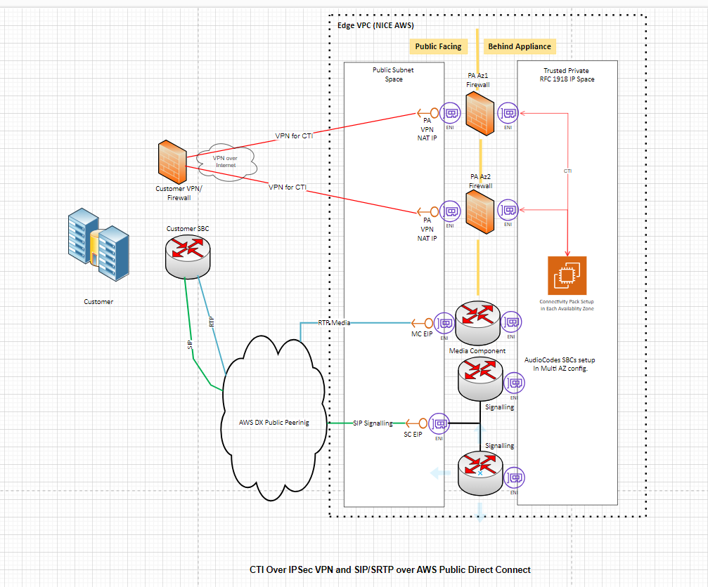
Model 1: CTI over IPSec VPN (VPN over Open Internet) + SIP/SRTP over AWS Public Direct Connect
CTI traffic goes through a VPN tunnel over the internet, while voice media (SIP/SRTP) flows over the Direct Connect link.
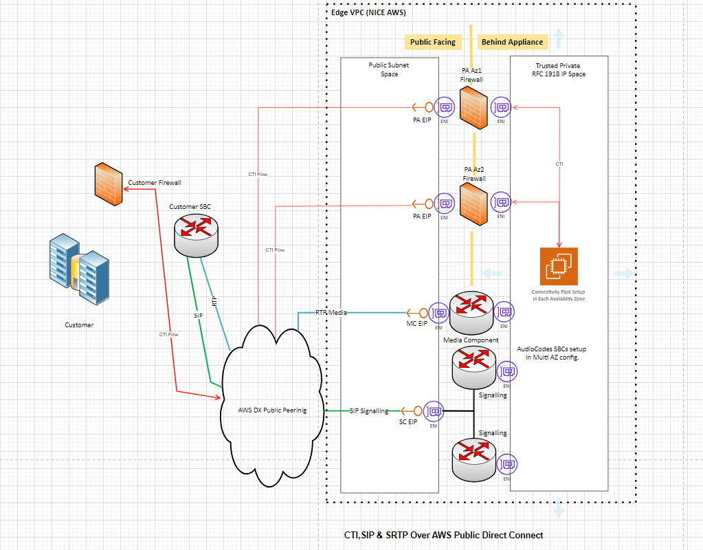
Model 2: CTI, SIP & SRTP all over AWS Public Direct Connect
All traffic (CTI signaling and voice media) flows over the Direct Connect link.
Model 3: CTI Over IPSec VPN (VPN over AWS Public Direct Connect) and SIP/SRTP over AWS Public Direct Connect
Use your existing AWS Public Direct Connect connection to establish an IPsec tunnel exclusively for CTI traffic. SIP and RTP traffic will continue to flow directly over AWS Public Direct Connect, outside the IPsec tunnel.
Prerequisites
Before you begin, confirm the following:
AWS Account: You have an active AWS account with permissions to provision Direct Connect ports and virtual interfaces.
Bandwidth planning: You have determined the required bandwidth based on your call volume. AWS Public Direct Connect supports speeds from 50 Mbps up to 400 Gbps.
High availability: It is recommended to design for high availability. AWS recommends at least two Direct Connect circuits per data center for redundancy.
Public IP addresses: You have public IPv4 address space available for BGP (Border Gateway Protocol) peering. You can either use your own public IPs or request peer IPs from AWS (at an additional cost).
Customer IP prefix: You know the public IP prefix you plan to advertise to AWS (/29, /28, /30). These are the NAT (Network Address Translation) or public IP ranges used by your SBC and CTI connections.
Supported ACD platforms: This setup supports Cisco (JTAPI) and Avaya (DMCC and SIPREC) integrations.
Dedicated or Hosted Connection? Choose between a dedicated connection or a hosted connection. A dedicated connection is a direct physical link to AWS and usually takes longer to set up. A hosted connection uses a partner provider and is faster to deploy. Both options are supported.
For Model 3 (CTI Over IPSec VPN (VPN over AWS Public Direct Connect) and SIP/SRTP over AWS Public Direct Connect), you also need:
-
An active Direct Connect Public VIF with an established BGP session.
-
The on-premises router must advertise the public IP prefix containing the IPsec endpoint.
-
The advertised prefix must pass the standard Direct Connect public prefix verification process.
-
The IPsec endpoint IP must fall within the advertised prefix.
Configuration
For more information, see the AWS Direct Connect User Guide.
Step 1: Create the Direct Connect Connection
-
Log in to the AWS Management Console and open the Direct Connect service.
-
Create a new connection and select the location closest to your data center.
-
Choose the port speed based on your bandwidth needs.
-
If you want high availability, create at least two connections.
-
Complete the setup process with your network provider. This includes establishing the physical connection between your data center and AWS.
Step 2: Create a Public Virtual Interface (VIF)
A Public VIF allows you to reach AWS public services (including CXone public endpoints) over Direct Connect.
-
To create the Public VIF, you must define the following:
-
a VLAN
-
your BGP ASN
-
your router peer IP
-
Amazon router peer IP (AWS provides this, or you specify your own from your public IP block)
-
the public IP prefix that your network will advertise to AWS
-
-
Once you submit the Public VIF configuration, AWS provisions the interface and prepares it for routing.
Step 3: Configure Routing with BGP
BGP (Border Gateway Protocol) is the routing protocol that exchanges route information between your network and AWS.
-
On your edge router or firewall, configure a BGP session with the Amazon peer IP and ASN.
-
Advertise your public IP prefix (the NAT/public range for your SBC and CTI systems).
Only advertise the public IP addresses used for Engagement Hub (Multi-ACD/Open) traffic. Do not advertise large or unrelated IP ranges. If you advertise too many IPs, other types of traffic may start using Direct Connect. This can cause routing problems and increase bandwidth usage.
-
Filter incoming routes carefully. AWS advertises all of its public IP ranges over Public DX. You should restrict your routing to accept only the prefixes needed for Engagement Hub (Multi-ACD/Open). In certain regions, NiCE Professional services provides specific public IP ranges for CTI server IPs, SBC signaling IPs and Media component IPs.
If you accept too many routes, you may disrupt your network routing or send unwanted traffic over Direct Connect.
-
Verify that the BGP session comes up and that routes are exchanged. You can check BGP status in the AWS Direct Connect console.
Step 4: Configure Your Network Equipment
Customer Firewall
-
Allow outbound and inbound traffic for the following protocols and ports on your public IP prefix:
-
CTI traffic: TCP on the port(s) used by your ACD (e.g., JTAPI for Cisco, DMCC for Avaya).
-
SIP signaling: UDP/TCP port 5060 (SIP) or 5061 (SIP-TLS).
-
RTP/SRTP media: UDP port range as defined by your SBC configuration.
-
-
If using Model 1 (CTI over VPN), configure an IPsec VPN tunnel from your firewall to the NiCE VPN endpoint for CTI traffic only. SIP/SRTP media flows directly over the Direct Connect link.
If using Model 3 (CTI Over IPSec VPN (VPN over AWS Public Direct Connect), utilize your existing Public Direct Connect connection to establish an IPsec tunnel exclusively for CTI traffic. SIP and RTP traffic will continue to flow directly over AWS Public Direct Connect, outside of the IPsec tunnel.
Customer SBC (Session Border Controller)
-
Configure your SBC to route SIP signaling and RTP/SRTP media toward the public IP addresses provided by NiCE Professional Services (SC EIP for signaling, MC EIP for media).
-
Ensure the SBC uses the public IP address from your advertised prefix as its source address.
-
All communication over the Public Direct Connect link must use public IPv4 address space. Private (RFC 1918) addresses do not work over a Public VIF.
Step 5: Coordinate with NiCE Professional Services
Contact NiCE Professional Services to share:
-
The public IP prefix you are advertising to AWS.
-
The AWS region you are connecting to.
-
Your chosen connectivity model (Model 1, 2 or 3).
NiCE Professional Services provides you with:
-
CTI server public IPs
-
SBC signaling public IPs
-
Media component public IPs
Step 6: Configure Your ACD Integration
For Cisco (JTAPI)
-
In the NiCE CXone administration portal, configure the telephony system with the Cisco JTAPI connection details (server IP, credentials, extensions).
-
Verify that CTI traffic (call events, hold/resume signals) reaches the CXone CTI servers through either the VPN (Model 1 or 3) or the Direct Connect link (Model 2).
For Avaya (DMCC & SIPREC)
-
Configure the Avaya DMCC or SIPREC integration in NiCE CXone with the appropriate server details.
-
Verify that signaling and media traffic route correctly over the Direct Connect link.